How to Find the Dominant Fouling Mechanism

In the following blog post we will take the information from previous articles “How Heat Exchangers Foul in Different Fluid Phases” and “What’s in The Fouling Deposit?” to identify the dominant fouling mechanism by evaluating process conditions and feed testing results. Once we understand the mechanism, we will be able to devise the best mitigation strategy.
Fouling in Single Phase Liquids and Gases
Deposition of particles causes fouling in such services. Some particles remain chemically unchanged after deposition (like already-formed coke, inorganics), while others- usually organic particles - transform into coke-like material. Deposit analysis informs us whether the particles belong to the first or second category. If the presence of one type of particle is predominant (say, >80%of the deposit), we investigate its origin and address the problem there. If we find both types, we need to tackle two or more sources. Feed (fluid entering the heat exchanger) tests allow us to check for any unexpected material, particularly inorganic substances not involved in the process.
Here are few examples: iron sulfide indicates corrosion somewhere in the flow circuit; coke (H/C < 0.70) originates from an upstream high temperature source like a hot distillation column or a fired heater; salts could indicate an inefficient desalting process or could be inherent to the process. For organic material with H/C between 0.80 and 0.95, the mechanism involves deposition plus conversion within the heat exchanger.
The deposition process, governed by the fluid shear stress at the wall, is part of the fouling mechanism. So, the typical mechanism involves the presence of particles, their deposition rate determined by the shear stress, and thermal conversion of some particles.
Boiling/Reboilers
Deposit analysis will reveal whether the fouling is a result of the common mechanism of a wet-dry wall (predictably, the deposit will be mostly organic), or due to deposition of carryover material (likely to be inorganic).
When organic, several methods can be used to decipher the mechanism:
- Testing the feed for precursors which maybe polymeric material or precursors to it (for instance, dienes).
- Operating conditions simulation, using a reliable heat exchanger software tool like Hexxcell Studio™, to know if the wall temperatures can cause film boiling and accelerate the fouling mechanism. It is important to combine this information with an understanding of the feed material – does it polymerize within a particular temperature range?
- A visual examination of the fouled tube bundle, revealing if fouling is concentrated in certain areas, usually where the wall temperature is highest. This is easier to see on the shell side.
A similar strategy is applicable to heat exchangers not classified as reboilers but used to vaporize the feed to a process unit. These feeds may contain organic precursors which form polymers which deposit and convert to coke-like material. With the help of deposit analysis to confirm whether the fouling is organic, a test of the feed for the precursors and H/C ratio verification (see later in this article), we can understand the fouling mechanism.
Overhead Condensers
Deposit analysis will reveal whether the foulant is precipitated salts or other inorganics, such as corrosion products, carried over from the top of the distillation column. It is not unusual to find some organics mixed with this material, but typically they aren't the primary cause of fouling.
After identifying the material, a simulation can indicate whether the wall temperature conditions are right for salt precipitation. If these conditions are localized, a visual inspection of the tube bundle can identify areas where deposits predominantly accumulate. If methods like water washes are used to dissolve salts, localized fouling suggests that the water isn't reaching these areas.
There are cases where vapor phase effluent from a reactor is condensed in heat exchangers. Usually, a comparable mechanism of salt precipitation (based on the cold tube wall temperature) is applicable in these cases.
Using the H/C Ratio of the Deposit
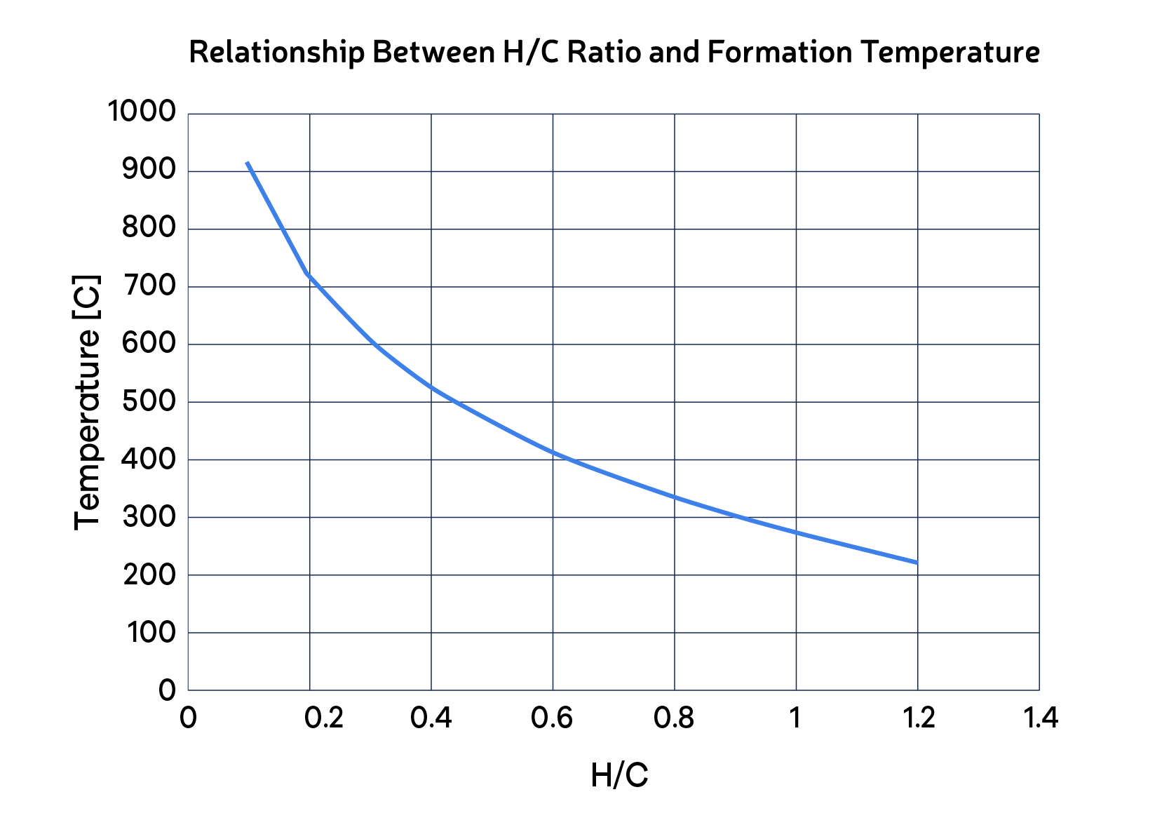
As defined in the previous articles, we can distinguish "coke" and "coke-like" material based on the atomic H/C ratio. This indicator can be instrumental in recognizing the temperature exposure of the organic portion of the deposit and connecting it with the fouling mechanism. For instance, if the H/C ratio of the deposit is 0.40, the coke was formed at around 520 C (Fig. 1). Since heat exchangers operate at much lower temperatures, we know that coke originated from an upstream furnace, column, or reactor. Alternatively, if H/C = 0.83 (as the example in the article “What’s in the Fouling Deposit”), the respective temperature is approximately 320 C. If the heat exchanger operates within this temperature range, we can conclude that the coke-like material was formed in the heat exchanger (deposition of organic precursors followed by thermal conversion).
Conclusion
By integrating deposit analysis, understanding of the feed content, and heat exchanger operating conditions, we can establish how and why a heat exchanger fouls. Factors such as precursors in the feed, increased deposition due to low wall fluid shear, temperature conditions favoring film boiling or salt precipitation, localized high temperatures and low velocities, all contribute to the fouling mechanism. Once we pinpoint the conditions responsible and the origin of precursors, we can determine what steps can be taken to mitigate fouling and its economic impact.
In the upcoming article, we will explore fouling mitigation in operating heat exchangers dealing with single phase liquids or gases, using hardware technologies.