How Heat Exchangers Foul in Different Fluid Phases
You are dealing on a daily basis with heat exchangers that foul. You may have been looking for solutions to the problems. Antifoulants, tube coatings, inserts. You are probably so fed up with it that you may have decided tore-design the unit in the hope that higher velocities will solve the problem. But have you ever considered that to find an appropriate solution you need to understand what the causes of fouling are in your specific system? Surely, mechanisms leading to fouling in gas systems differ significantly from those driving deposition in kettle reboilers, and therefore the solutions are different.
In this blog, we investigate the causes of fouling by looking at the different types of deposits that form on heat transfer surfaces and how fouling mechanisms depend on the fluid phase – single phase, boiling, or condensing. The descriptions here are based on examples from the Oil & Gas industry but the generic mechanisms are applicable in other industries albeit with different chemistries for the precursors and deposits.
Heat exchangers foul via the accumulation of unwanted, material on the heat transfer surface. This material could either be the results of species that are generated through a chemical reaction into the final fouling depositor they could enter the heat exchanger via the process stream, or even from within it, typically through precipitation. The mechanism of fouling is different according to the fluid phase. A thorough understanding of the precursors and the causes of fouling is fundamental in order to adopt mitigation measures and optimise cleaning schedules.
Precursors of Fouling Deposit
Fouling is primarily caused by two precursor types - contaminants or suspended solids which are not part of the fluid - such as corrosion products, coke, salts - and solids precipitated from the fluid, like asphaltenes, polymers, and some salts. Precursors can precipitate either upstream or inside the heat exchanger. The contaminants and precipitated salts deposit without any chemical change in the heat exchanger conditions, whereas organic precursors thermally break down to coke-like material over time and temperature.
In our terminology, “coke” is defined as an organic material which has undergone thermal conversion at high temperatures (450+ C) and can no longer dissolve in aromatic solvents like toluene; for instance, coke developed at the base of the vacuum column in an oil refinery. The term “coke-like material” refers to organic precursors which partially transform within the heat exchanger due to the high tube wall temperature (250-350 C). A clear difference between the two is the atomic hydrogen-to-carbon ratio (H/C)which will be usually < 0.70 for coke and 0.80-0.90 for coke-like material formed in heat exchangers. The carryover of inorganic material, particularly corrosion products like iron sulfide, can cause fouling in heat exchangers that otherwise wouldn’t foul from other mechanisms.
Let’s now dive into the specific systems we mentioned above single-phase, boiling and condensing and how the fouling process varies.
Single Phase Liquid or Gas Systems
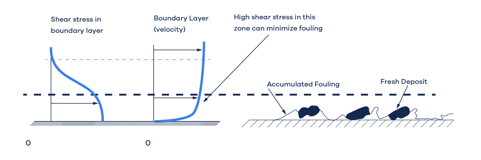
Single-phase heat exchangers foul because of the deposition of the two types of precursors. Gradually, the deposit layer compacts and hardens, creating a resistance to heat transfer and clogging the flow route. If the tube wall is warmer than the fluid (the fluid is being heated), the organic precursors transform into coke-like material. The rate of deposition depends largely on the fluid's shear stress at the tube wall (the higher the shear, the lower the rate of deposition) and the affinity between the surface and the precursors – some surfaces are “stickier” than others. In most situations, wall shear stress of > 10 Pa will reduce fouling. Fig. 1 illustrates this process.
Boiling/Reboilers
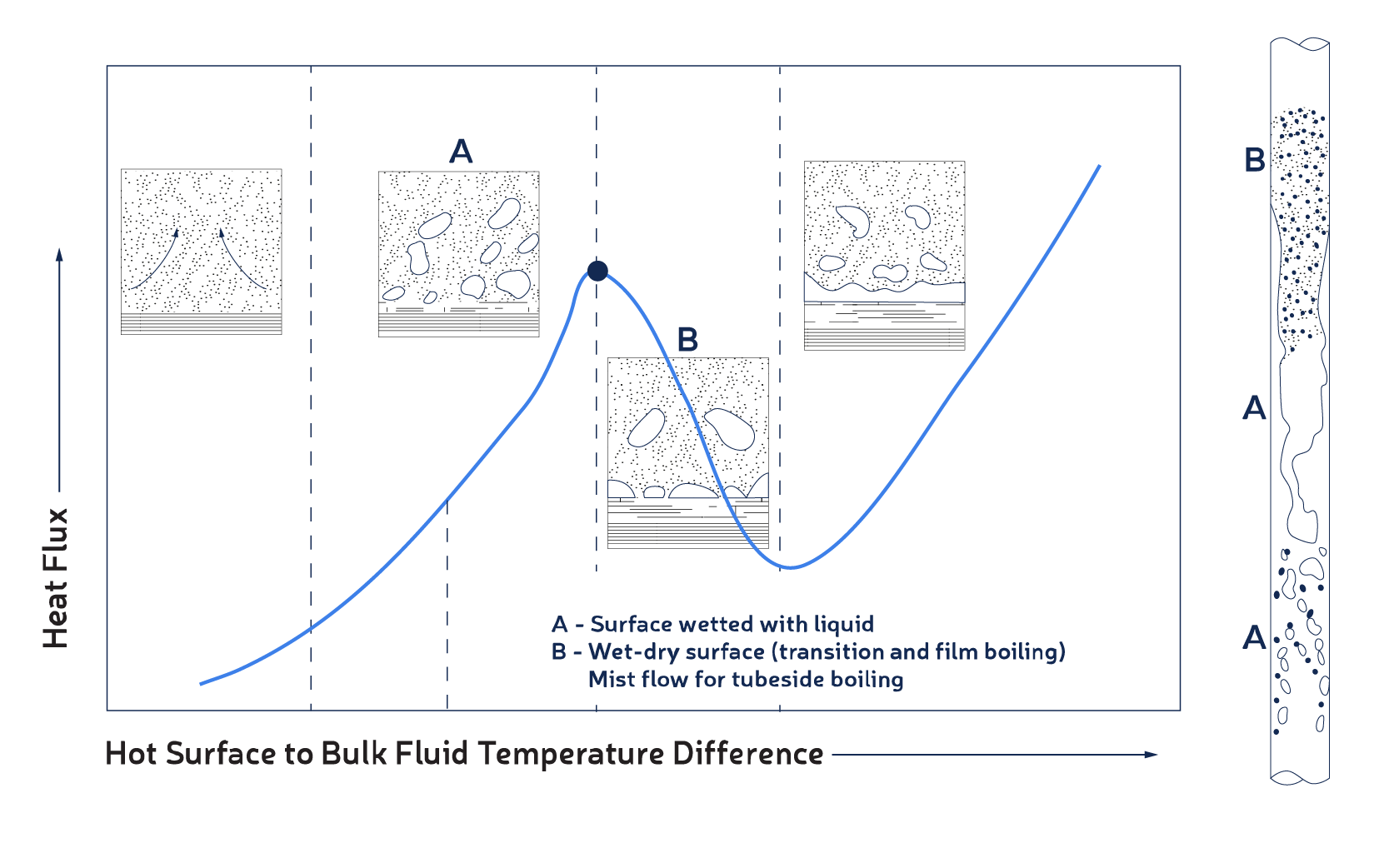
When a liquid containing an insoluble precursor vaporizes along the tube wall, it leaves that precursor behind. The solid doesn't leave the surface with the vapor but stays on it. If the precursors are organic, they will transform into coke-like material gradually (as in reboilers); if inorganic, they will form a hard layer gradually (like salts in a steam generator). This process is faster if the tube wall temperature is too high to maintain liquid at the wall. If the boiling resembles pool boiling in the nucleate boiling regime, the surface tends to remain wet with a liquid film; but if it is in the transition boiling regime, the surface has wet-dry conditions and solids will deposit at a faster rate. This event is prevalent in reboilers and feed preheat heat exchangers in hydroprocessing where the heated fluid contains polymers.
The phenomenon of nucleate versus film boiling is demonstrated in Fig.2, which depicts a typical boiling curve of heat flux against temperature difference and how boiling flow regimes appear in a vertical tube.Under condition A, vapor bubbles escape out of the liquid film on the surface, whereas under condition B, some part of the surface has vapor in contact with it. Condition B is where fouling occurs more frequently and faster compared to condition A.
Overhead Condensers
Overhead material may consist of dissolved salts that precipitate when in contact with a cold tube surface; for instance, chlorides in atmospheric overhead or in hydrotreating reactor effluent. The salts may not deposit on the tube wall as they can be washed away by the liquid flow, but they tend to accumulate in areas where liquid is insufficient due to low-flow zones such as in a dead-space beyond an outlet nozzle. Water channeled into the overhead or effluent can dissolve the salts and prevent build-up, but only if sufficient amount of water reaches the surfaces where deposition is likely to occur.
Conclusion
Heat exchangers foul due to different mechanisms depending on the fluid phase and the availability of precursors. An understanding of the mechanisms is the first essential step to evaluate mitigation actions and find long term solutions to fouling problems. Such understanding is also useful at the design stage to develop designs most resistant to fouling.
In the next article we will see how to accurately quantify the elements/compounds in the fouling deposit and to determine whether it is dominated by organic or inorganic material.