How to Mitigate Fouling by Changing Heat Exchanger Design or Fluid Conditions

In the article “How to Mitigate Fouling in Heat Exchangers Using Hardware Technologies” we reviewed the strategies that use external hardware to minimise fouling. This time, we’re turning our focus to how adjustments in the geometry of the heat exchanger or changes in fluid conditions can mitigate fouling.
As highlighted in the article “How Heat Exchangers Foul in Different Fluid Phases” fouling occurs due to different mechanisms depending on the phase of the fluid:
- In single phase flows, fouling is mainly caused by the deposition of particles.
- In boiling services, high wall temperatures can create wet-dry conditions, which leads to deposition of solids and their conversion to coke-like material.
- In condensing services, salt precipitation at the tube wall — combined with flow patterns that promote deposition or prevent salts from dissolving — leads to fouling.
- Note that if solids are carried into the heat exchangers from upstream, fouling can occur regardless of fluid phase and design.
Shear Stress in Single Phase Flows
Deposition of particles is governed by two opposing forces, fluid shear at the wall (τ)and the attraction between solids and the tube surface. In a given scenario where surface characteristics and particles type remain unchanged, shear stress determines deposition rates. This behaviour is evident in both liquids and gases. In order to reduce fouling due to deposition, increasing the shear stress has proven to be very effective.
Whilst shear stress is associated with velocity (V),it represents a fundamental parameter since it also accounts for fluid properties, mainly viscosity. Field and pilot-plant data has revealed that the fouling rate (increase in fouling resistance per day) correlates to (τ) -a on the tube side, and (τ)-b on the shell side, where a is in the range of 1.0-1.2 and b is approximately 0.6. While extensive data exists for the tube side, information on the shell side is comparatively limited, making the corresponding relationship more uncertain. Another source of uncertainty on the shell side is the presence of multiple flow paths and the inability to precisely calculate velocities and shear stresses. As a result, crossflow shear stress is typically used as an approximation.
The exponential relationship between fouling rate and shear stress denotes that an increase in shear will eventually stabilise the fouling rate, as depicted in Fig. 1. Tube-side data indicates this plateau occurs at around 10-12 Pa, beyond which further increasing shear stress offers little benefit. The suggested tube-side shear stress for minimum fouling is 10 Pa, which typically equates to velocities between 2.0-2.5 m/s for most liquids. Fig. 1 illustrates the fouling rates for three different fluids, varying by an order of magnitude, yet reaching exponential lows at similar shear stress values.

The most effective way to increase tube-side velocity is by adjusting the number of tube passes. For instance, changing from two to four passes doubles the velocity and reduces the fouling rate by approximately 60%. Alternatively, changing from four to six passes increases velocity by 1.5 times and reduces fouling by about 40%. The trade-off for increased velocity is an increase in pressure drop which is proportional to V2*L, where L is the flow path length. Hence, when two passes are changed to four, both velocity and flow length double, resulting in an approximately eight-fold increase in the new clean pressure drop. That high a pressure drop may not be feasible, but it's important to note that fouling itself contributes to increased pressure loss — so in severe fouling conditions, an eightfold increase may already be occurring in actual operation.
From a practical perspective, it isn't possible to exceed a velocity of about 0.75m/s for liquids on the shell side. As the baffle spacing tightens to boost velocity, the flow is redirected from the crossflow component to various"leakage" paths without significantly increasing crossflow shear. Baffle spacing is also subject to fabrication constraints, with the standard minimum set at 20% of the shell diameter. Moreover, limited field data has been analysed for the shell side, and no pilot plant studies have been reported to establish shear stress guidelines. As a result, the general advice is to maintain shell side crossflow velocities at or above 0.75 m/s to minimise fouling.
Shell side deposition is also affected by the presence of low velocity circulation zones (also known as "dead zones") where particles can become trapped and aren't swept away by the fluid force. These zones are formed due to the physical impact of flow direction changes as fluid moves around the edges of the baffles, as seen in Fig. 2. Deposits in these corners can be minimised by ensuring crossflow and window velocities are roughly equal, thereby reducing the size of the dead zone. In addition, a large spacing in the outlet and inlet areas leads to low flow near the tubesheets, thus promoting deposition.

Reducing Fouling in Reboilers
As outlined in the article “How Heat Exchangers Foul in Different Fluid Phases”, the presence of a wet-dry wall and the film boiling contribute to the deposition of insoluble substances—such as polymers or salts—that adhere to the surface and can gradually undergo thermal degradation, forming a coke-like residue. Three conditions can contribute to this mechanism:
- The presence of insoluble material.
- A surface temperature so high that a liquid film cannot be maintained on the tube wall.
- Excessive evaporation or vapour flow - especially locally - so that there isn't enough liquid to keep the surface wet (vapour blanketed surfaces).
It may not be feasible to avoid the presence of insoluble precursors since they are part of the process. However, their formation or quantity can be minimised. An example is the cause of fouling in oil-refining reboilers, dienes. Changing the feed composition to the process unit can minimise the component carrying the dienes.Alternatively, controlling reboiler temperatures can limit the conversion of dienes to insoluble polymers.
The occurrence of wet-dry surfaces can be effectively managed by controlling the temperature of the heating medium and ensuring that liquid reaches the entire boiling surface. A surface covered with liquid is less prone to deposition, thereby reducing the risk of fouling. Lowering the heating medium temperature decreases the temperature gradient driving heat transfer, which might slightly reduce heat duty. However, this potential loss is often smaller than the impact of fouling or can enable longer operational periods before cleaning becomes necessary.
The phenomenon of excessive vapour flow can stem from two causes:
- The operation of the reboiler may sometimes result in insufficient liquid being supplied. When the heat duty remains constant, this leads to the generation of excessive vapor.
- Flow patterns within the heat exchanger can cause parts of the heat transfer surface to be deprived of liquid, leaving them blanketed by vapour. This issue is also common in steam generators if proper liquid circulation is not maintained.
Fig. 3 shows a reboiler tube bundle that experienced localised fouling. This occurred because the area with the highest heating medium temperature, located beneath the outlet nozzle, also handles the greatest volume of vapour within a relatively small space. As a result, the surface is starved of liquid, creating conditions for polymer deposition. Furthermore, the lack of proper cooling leads to another problem: the tubes overheat and buckle under thermal expansion forces.

Design Strategies to Mitigate Fouling in Condensers
Overhead condensers often experience fouling due to the precipitation of salts as the condensing fluid cools. To mitigate this issue, two design strategies can be employed:
- The heat exchanger should be designed to promote uniform condensation.This ensures that vapour evenly contacts all surfaces, while the condensed liquid can help remove some of the precipitated salts.
- A wash stream can be introduced into the incoming vapour to dissolve precipitated salts. For instance, water can be used to remove water-soluble salts, provided this aligns with the process requirements. In this approach, it is critical to ensure that the wash stream effectively reaches all potential fouling locations to maximise its effectiveness.
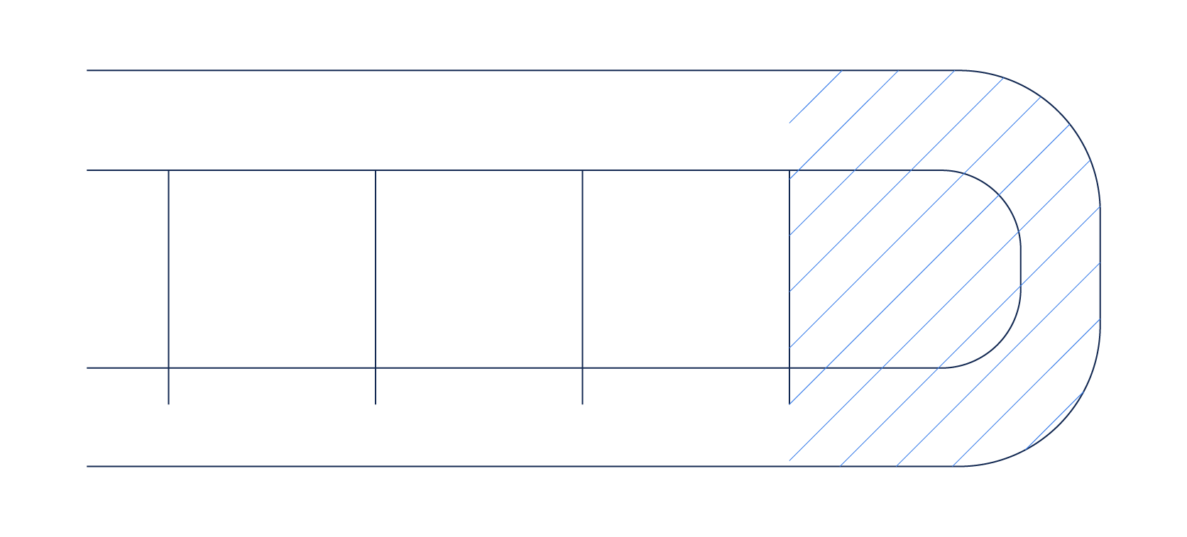
Fig. 4 illustrates the shell side exit in a condenser with U-tubes, highlighting an issue with the nozzle's placement.Its position prevents most of the vapour, condensed liquid, or wash stream from reaching the shaded area, leading to rapid fouling in that region. A potential solution is to reposition the nozzle further to the right or shorten the tube length so that the entire heat transfer surface is situated to the left of the nozzle.
Fouling Mitigation Expense
The techniques outlined above, along with those explained in article “How to Mitigate Fouling in Heat Exchangers Using Hardware Technologies”, come with associated costs - ranging from capital investment and engineering to tube bundle replacements, increased pressure drops and, most significantly, process adjustments. While the cost of fouling mitigation actions may seem high, it’s essential to consider the long-term savings they can deliver. Evaluating the return on investment over time often reveals the true value of these measures. In a future blog post, we’ll take a closer look at fouling costs and the benefits of mitigation.
In the Next Article
In the upcoming article, we’ll focus on cleaning fouled heat exchangers: a critical step in managing fouling costs, even though it isn’t a direct mitigation strategy. We’ll examine various cleaning methods, comparing their costs and effectiveness, and discuss the consequences of neglecting to clean a heat exchanger thoroughly. Stay tuned for insights into how proper heat exchanger cleaning can play a pivotal role in minimising fouling-related expenses.